
3.1 Introduction
The milling machine, invented by Eli Whitney in 1818, carries out cutting operation on a workpiece with a revolving cutter as the workpiece is fed against it. A milling cutter has a series of cutting edge on its circumference. Each acts as an individual cutter during the cycle of rotation. Depending upon the type of milling operation, the cutters used on a milling machine have different shapes and sizes. These cutters are held on the arbor or attached directly to the spindle to carry out the operation. The milling machine is the most versatile machine for machining flat or formed surfaces with excellent finish and accuracy. The various operations that can be performed on it are cutting angles on workpieces, slots, gear teeth, boring and surface machining.
3.2 Classification of milling machines
Milling machines are classified in a variety of ways.
- According to the drive, milling machines are classified as
- Cone-pulley belt drive
- Individual motor drive.
- According to design, milling machines are classified as:
- Column and knee-type milling machine
- Planer milling machine
- Fixed bed-type milling machine
- Special milling machines, such as rotary table, duplicating and profiling.
- According to the position of the spindle, milling machines are classified as:
- Horizontal spindle milling machines
- Vertical spindle milling machines
The spindle of the horizontal milling machine is horizontal to the worktable, while the spindle of the vertical milling machine is at right angles to the worktable. In a vertical milling machine, the cutter can be raised or lowered by an adjustment of the spindle head. In all milling machines, the worktable can be moved to any position to carry out the operations.
3.3 The Principal parts of a milling machine
A description of the principal parts of a milling machine follows.
- Column : The main casting of a milling machine is known as the column. It encloses and supports all the parts of a milling machine.
- Knee: It is a unit attached in front of the column. It moves up and down on the slide ways and encloses the feed change gearing mechanism.
- Table : It is an attachment provided at the top of the knee. It is used for holding workpieces for machining and can be moved in a longitudinal as well as a crosswise direction.
- Spindle: It is a large shaft located at the top of the column having a tapered hole in front of it. The tapered hole is used for holding arbors and cutting tools.
- Over arm : The portion at the top of the column above the spindle is called the over arm. It is used for supporting arbors and can be moved forward and backward.
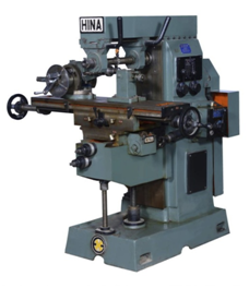
Figure 4.1 – Milling machine
3.4 Operations performed on milling machine
- Face Milling – machining flat surfaces which are at right angle to the axis of the cutter.
- Plain or Slab Milling – machining flat surfaces which are parallel to the axis of the cutter.
- Angular Milling – machining flat surfaces which are at an inclination to the axis of the cutter.
- Form Milling – machining surfaces having an irregular outline.
- Gear cutting
3.5 Specification of milling machine
Table 3.2 – Cutting speeds (in m/min)
Material | High speed steel | Carbide tip tools | ||
Rough milling | Finish milling | Rough milling | Finish milling | |
Cast iron | 15-18 | 25-32 | 60-70 | 115-135 |
Malleable iron | 25-35 | 35-50 | 90-110 | 140-165 |
Steels | 20-30 | 25-35 | 100-110 | 100-120 |
High-carbon steel | 15-25 | 20-30 | 90-100 | 100-110 |
Alloy steel | 18-25 | 20-30 | 85-100 | 100-110 |
Copper and its alloy | 35-65 | 50-80 | 200-220 | 300-320 |
Aluminium and its alloy | 120-140 | 220-250 | 250-290 | 350-370 |
Magnesium and its alloy | 130-150 | 240-270 | 270-300 | 380-400 |
Stainless steel | 25-30 | 30-40 | 80-100 | 100-120 |
The cutting feed of a material is the distance advanced by the cutter in one complete revolution. It is generally expressed in mm/min. The normal practice is to give as much feed as the machine can withstand.
Milling Job :
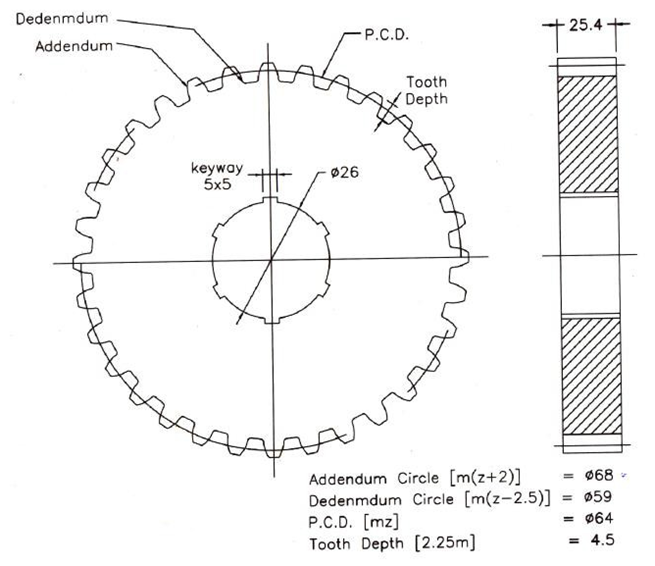
Figure 3.2 – Milling job (Drawing)
Calculation for gear cutting on milling machine:
Raw material | Cast iron | |||||||||
Module | 2 | |||||||||
No. of teeth | 32 | |||||||||
Cutter selection | Now for 32 teeth cutter no. is 4 | |||||||||
| Cutter No. | No. of teeth | Cutter No. | No. of teeth |
| |||||
1 | 135 | 5 | 21 to 25 | |||||||
2 | 55 to 134 | 6 | 17 to 20 | |||||||
3 | 35 to 54 | 7 | 14 to 16 | |||||||
4 | 26 to 34 | 8 | 12 to 13 | |||||||
Depth of cut | (2.25 m) 2.25 × 2 = 4.5 mm | |||||||||
Speed of cutter | 150 rpm (L and A selection of handle) | |||||||||
Table speed | 15 mm/min (Lever selection C) | |||||||||
Calculation for OD | m = OD / (T+2) OD = 2 × (32 + 2) = 68 mm | |||||||||
Indexing plate selection | 40 ÷ N = 40 ÷ 32 = 5/4 = 1 (4/16) | |||||||||
Indexing plate no. | Now, 16 no of holes are in plate no 1 front side so select it. In it 1 full revolution and 4 holes are to be revolved for every cutting teeth. | |||||||||
| Plate No. | One side | Other side |
| ||||||
1 | 13, 16, 18, 20, 23 | – | ||||||||
2 | 15, 17, 19, 21, 24 | 27, 28, 31, 37, 41, 47 | ||||||||
3 | 18, 19, 20, 23, 29, 33, 39, 43, 49 | 15, 17, 19, 21, 27, 31, 37, 41, 47 | ||||||||
Table travel | 100 point = 1 rev = 1 mm | |||||||||
Saddle travel | 1 rev = 5 mm | |||||||||
Calculation for gear cutting on milling machine:
Raw material |
| |||||||||
Module |
| |||||||||
No. of teeth |
| |||||||||
Cutter selection |
| |||||||||
| Cutter no. | No. of teeth | Cutter no. | No. of teeth |
| |||||
1 |
| 5 |
| |||||||
2 |
| 6 |
| |||||||
3 |
| 7 |
| |||||||
4 |
| 8 |
| |||||||
Depth of cut |
| |||||||||
Speed of cutter |
| |||||||||
Table speed |
| |||||||||
Calculation for OD |
| |||||||||
Indexing plate selection |
| |||||||||
Indexing plate no. |
| |||||||||
| Plate No. | One side | Other side |
| ||||||
1 |
|
| ||||||||
2 |
|
| ||||||||
3 |
|
| ||||||||
Table travel |
| |||||||||
Saddle travel |
| |||||||||
Actual Job Photographs :